| ENERGY SAVERS |
|
 |
| POWER |
| How it works ? |
| Motor ratings are so selected as to be able to deliver the maximum load for its application; but subsequently, only a few minutes of start-up, consume only 60 - 80% of the actual power drawn, and the balance is wasted in heat, noise and friction. |
| • |
The magnatron detects the lag between the voltage & current waveforms ,and
using this lag as a reference point,its proprietary algorithm sends a firing impulse to the scr to reduce/increase voltage & current to match the electricity supply exactly to demand torque load, this closed loop, cyclical exercise is repeated 50 times/second. |
| • |
How to select motors which give maximum saving : nola type energy saving micro controller , offer very high energy savings for those motors which draw less than 60% of its rated plate amps for at least 15% of operating cycle. |
|
|
 |
|
|
| How Magnatron Works ? |
| • |
When interfaced with ac induction motor it initially characterises the motor – this is a learning cycle! |
| • |
The micro controller records maximum operating parameters. |
| • |
These parameters are then continuously used to monitor motor efficiency. |
| • |
Micro controller ensures the maximum continuous rating of motor is matched exactly to varying load. |
| • |
Magnatron allows maximum power to motor in 1/50th of a second. |
| • |
Energy saving is achieved by means of closed loop feed back systems. |
| • |
Sensing circuits compare the voltage and current wave forms. |
| • |
This being industrial circuit current and voltage wave forms start at different time. |
| • |
The smaller the load the greater the lag in current wave forms. |
| • |
At no load, motor is least efficient and wave forms are farthest. |
| • |
Magnatron measures the distance between the two and compares this difference to an ideal operational distance. |
| • |
Difference between the actual waveforms and ideal is known as error voltage. |
| • |
The P.F is only used as a Reference Point - the Magnatron's objective is not to improve P.F ( Reactive Power) but to reduce Actual Power (KWH). Your Bill is based on the KWH and Reactive Power Billing is only a percentage of KWH (Real Power). |
| • |
This error-voltage is used to create a firing pulse, which determines duration of power supply to motor larger, the error voltage, shorter, the pulse and vice -a- versa. |
| • |
This is how microprocessor automatically adjusts the terminal voltage to match the load demand. |
| • |
This reduces motor dependent losses. |
|
| Actual optimization is related to extent of partial loading and its duration |
|
|
| FUEL |
| • |
Reduction of fuel consumption upto 15% on industrial boiler / burners, and industrial d.g. sets, and upto 20% on vehicles. |
| • |
Virtually total elimination of carbon monoxide and hydrocarbons and substantial reduction in total emissions. |
| • |
De-carbonisation of engines, carburrettor and nozzles. |
| • |
Prevention of carbon deposits in the above areas. |
| • |
Prevention of carbon deposits in the above areas. |
| • |
Increase in engine life, better pick-up and more power, as well as longer intervals between servicing and maintenance. |
|
 |
|
|
| Science |
| These high powered permanent monopole magnets convert the negative fuel to a positively charged fuel. |
|
|
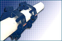
| WATER |
| • |
Prevention and removal of scaling, thus restoring and ensuring complete heat transfer and reducing energy bills!
NOTE: A 1mm scale increases energy consumption by 30% |
| • |
It restores full efficiency to r.o., d.m., and softening plants ensuring : |
| |
| |
Prevention of scaling from better quality of water. |
| |
Substantial increase in regeneration cycle. |
| |
Reduction in chemical dosage ensures high return on investment. |
|
| • |
No power, electricity, fuel, chemicals, maintenance or moving parts, therefore no pollution or wasted water |
| • |
Easily installed on pipes of any diameter, externally. |
| • |
All units are supplied with a 15-year, permanent power warranty. |
| • |
The higher the velocity, the better the performance ! |
|
 |
|
| |